DJ Add-on
To get your DJ Add-on working, you first need to assemble it before you can connect it to the badge.
HARDWARE
Interactive hardware overview
Hover over a component for a short explanation and to highlight its connections. Click a component to pin its details.
Open the original PNG diagram ↗
DJ add-on features
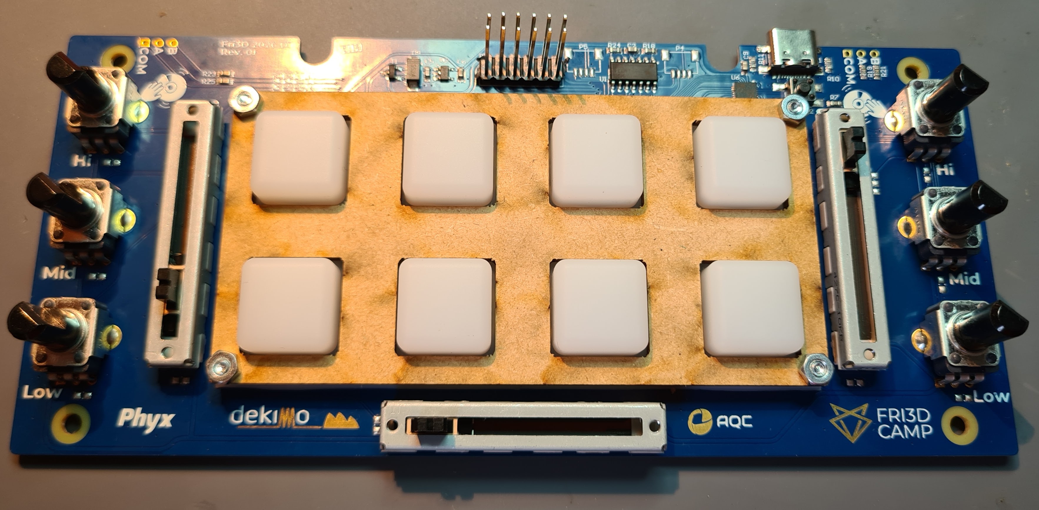
The DJ add-on consists of:
- 6 potentiometers
- 3 faders
- 8 buttons (in a 3x3 matrix)
- 8 WS2812 RGB LEDs (1 under each button)
- 2 connectors for rotary encoders
- 2 connectors for hard disk drives (see below)
You can find the design and source files in the GitHub repository
Step by step assembly guide
All components neatly packaged
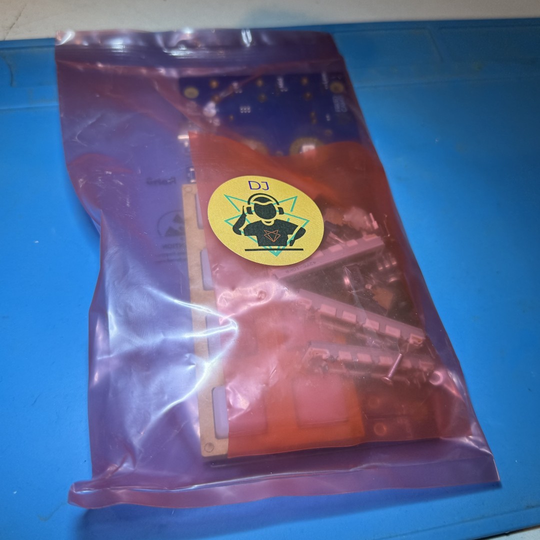
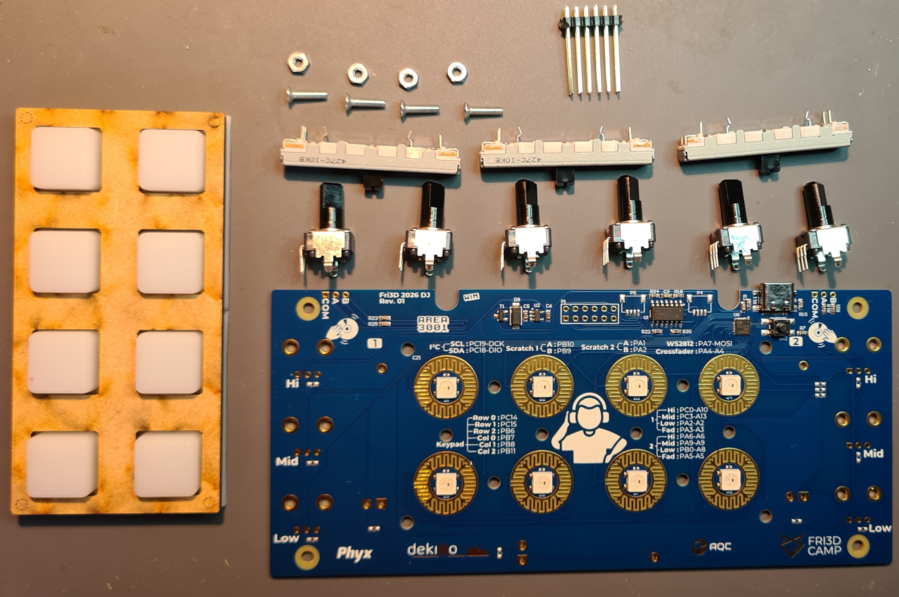
The package you received contains everything you need to build the DJ add-on
- DJ add-on printed circuit board
- 6 potentiometers
- 3 faders
- 8 silicone buttons
- 4 M3 screws
- a cover plate for the buttons
- 1 x 2x6 pin header with extra long pins
Mount the faders
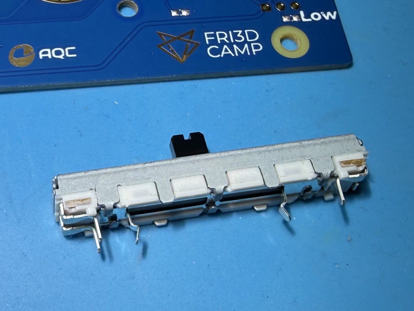
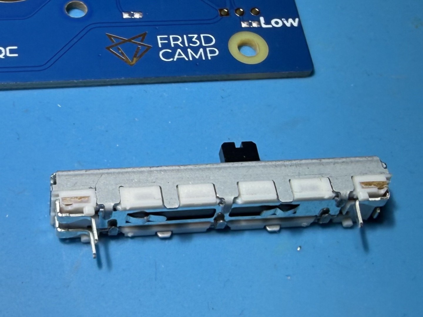
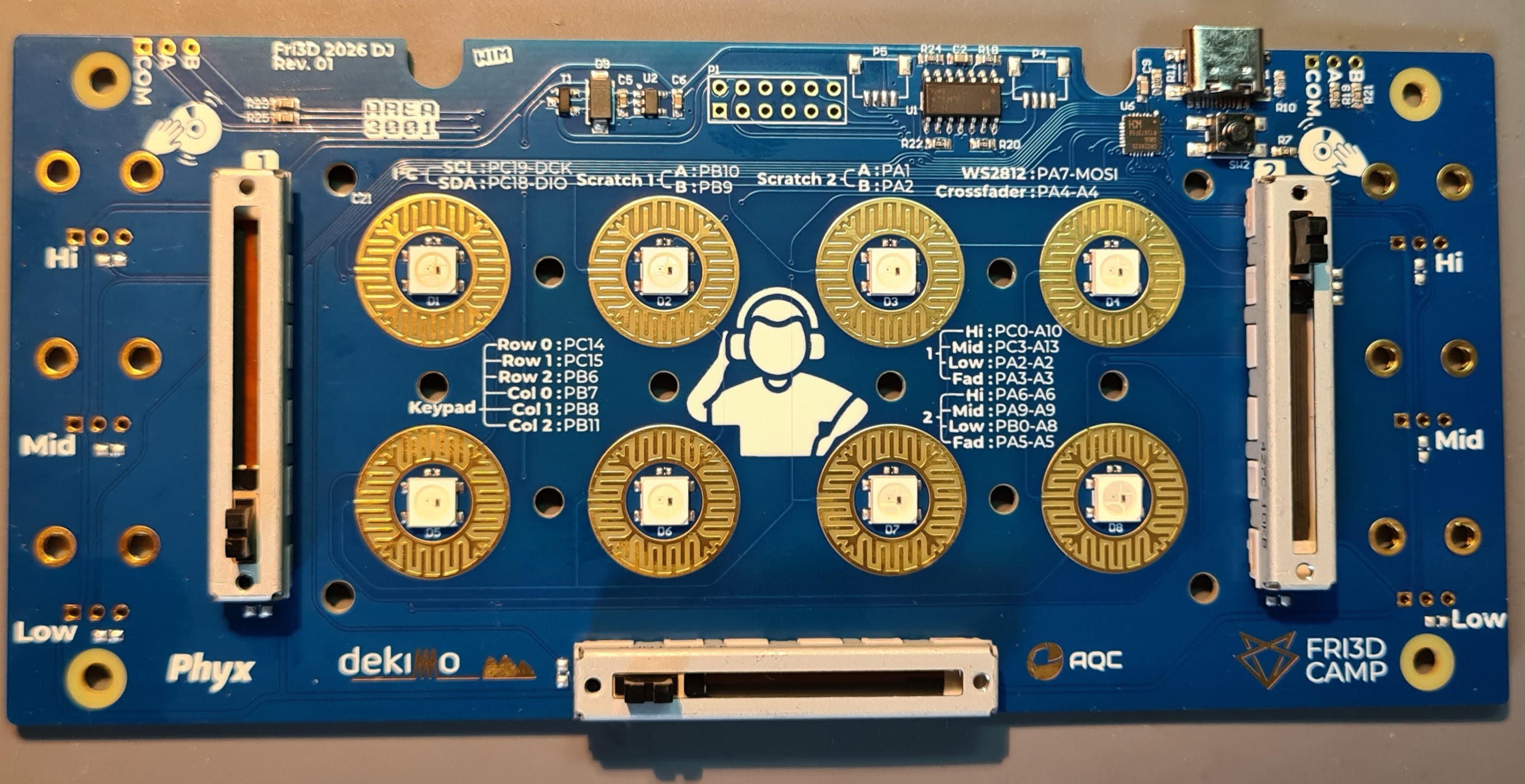
There are 3 faders to solder: 1 on the left, 1 on the right and 1 at the bottom. Bend the 2 middle legs of the fader flat, there is some room between the fader and the pcb, almost flush is good enough. Place them in the designated holes and solder them in place on the back of the PCB.
Mount the potentiometers
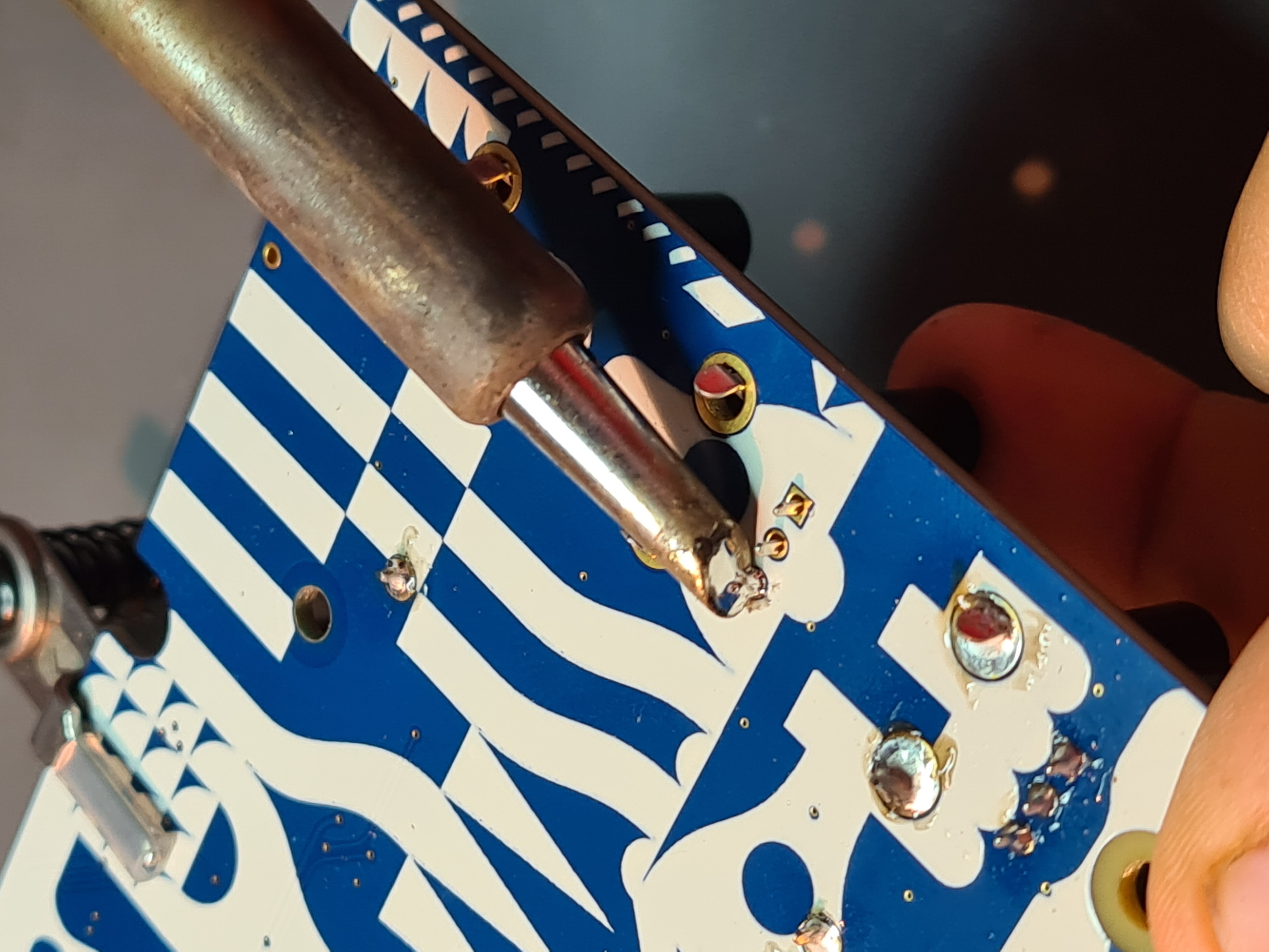
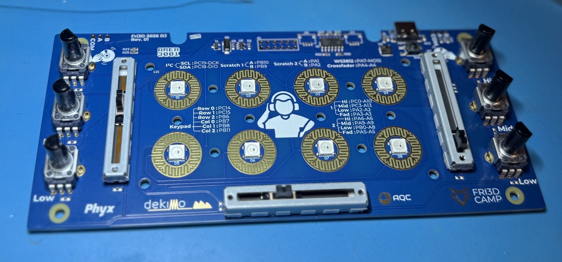
Do the same for the 6 potentiometers, 3 on each side. Click them into the designated holes and solder all contact points on the back of the PCB.
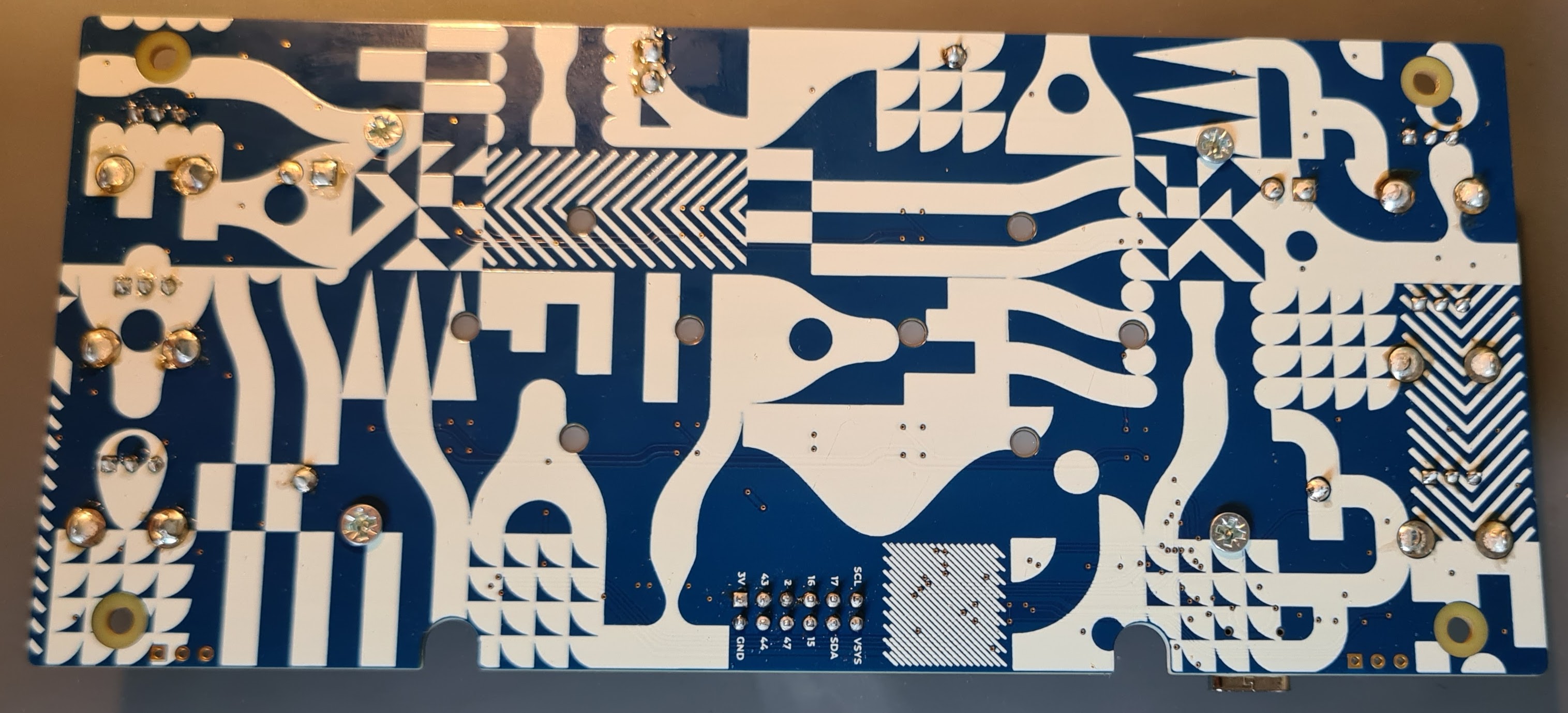
Solder the long pins
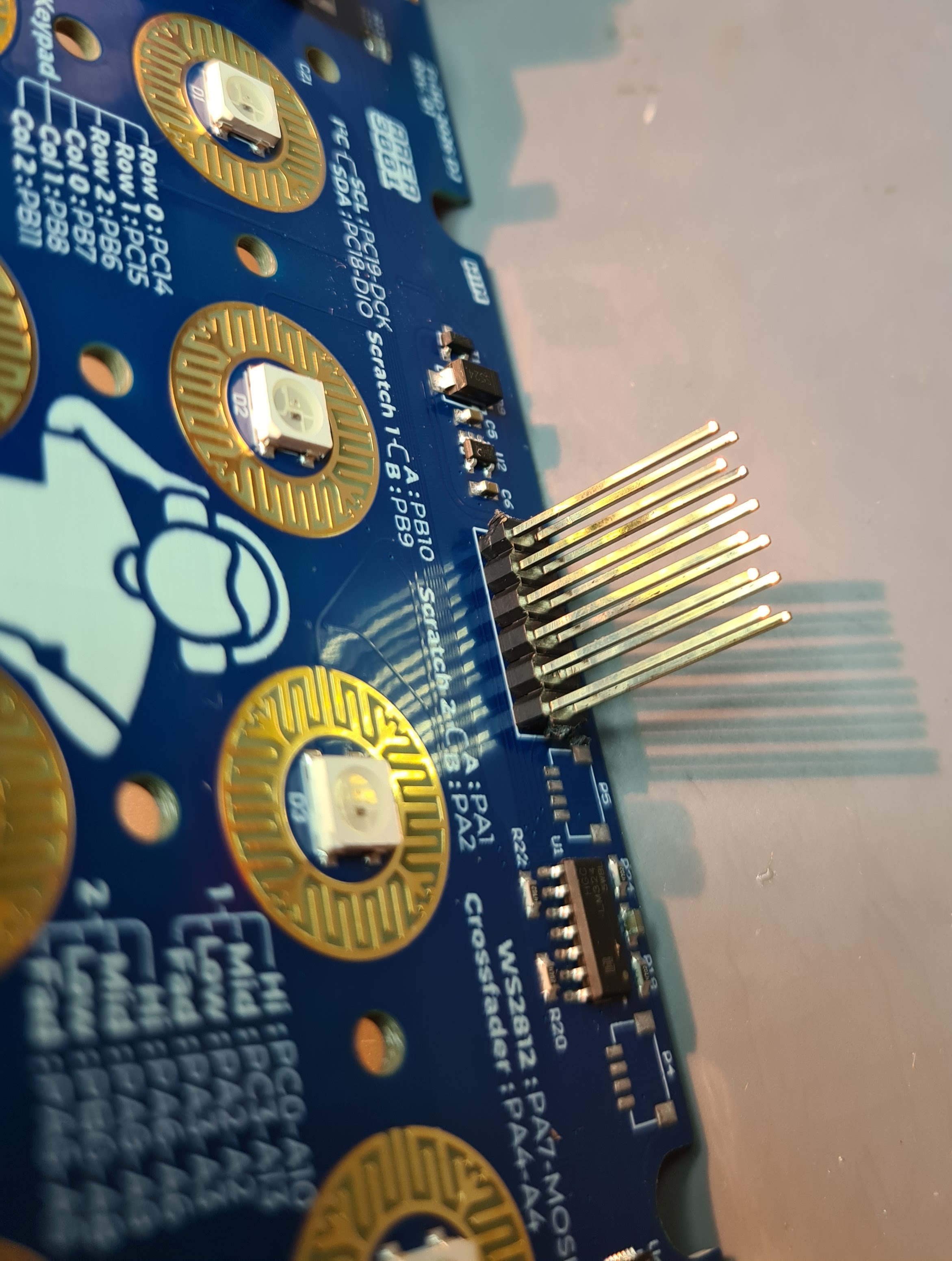
Place the long pins on the side with all the components. You can use another female connector (or even the badge) to keep the 2 loose pin strips neatly aligned while soldering.
Mount the silicone keys
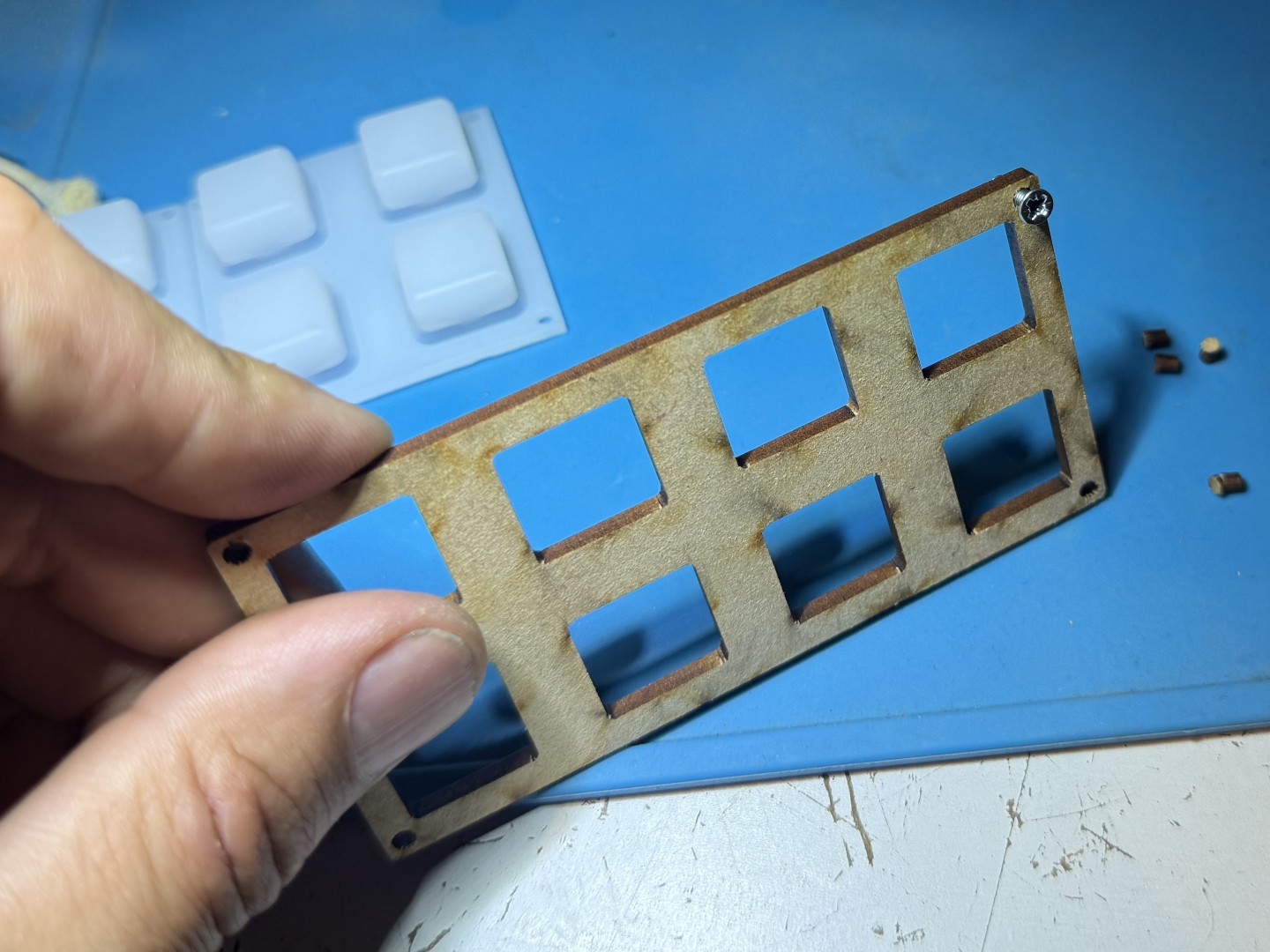
Place the silicone keys on the PCB and slide the wooden cover plate over them. Make sure the screw holes in each corner of the silicone layer, the PCB and the plate are nicely aligned. Then mount the 4 screws in the holes from the bottom side (the PCB side), and place the nut on the top side (the side of the wooden plate).
Connect 2 hard disk drives or rotary encoders
Classic computer hard disk drives always contain a round magnetic platter that is spun by a spindle motor. This spindle motor is (usually) a 3-phase brushless DC motor without sensors. So there will be 4 contact points going to the motor. The idea is that we use this spindle motor as an input device on the DJ add-on by connecting 3 of these 4 contact points to 1 of the encoder inputs of the DJ add-on. This also requires some soldering work. Our inspiration for this came from this instructable, where you can also find more information.
So we connect 2 of the 3 phases of the motor to the DJ add-on. Each of these produces a sinusoidal signal that is 120 degrees out of phase. Internally on the DJ add-on, comparators are mounted that convert these 2 sine waves into 2 square waves that can easily be measured by the encoder function of the CH32X035.
You can also connect classic rotary encoders to the DJ add-on. These will probably provide a more precise signal than the HDDs.
In the App Store of MicropythonOS you can find a simple DJ Add-on app that you can use to test whether your DJ Add-on works properly.
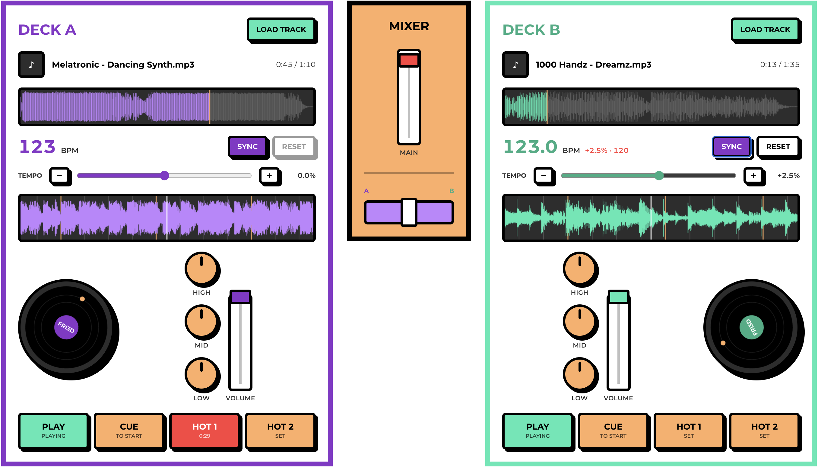
You can also try out your DJ Add-on right away in your browser with the Fri3d Scratcher: connect the DJ Add-on to your computer via USB, open the website and click "Connect controller". You can then load tracks and mix using the potentiometers, faders and buttons of your DJ Add-on.
Usage
The DJ add-on presents itself as a MIDI device. You can connect the DJ add-on to your computer via USB, or to your badge via the expansion connector. The DJ Add-on can communicate with the badge via both UART and I2C. The UART settings are 115200 8N1.
Want to get started as a DJ right away? Connect the DJ Add-on to your computer via USB and open the Fri3d Scratcher web application in your browser. It works via Web MIDI and lets you mix 2 decks with your DJ Add-on as a controller.
Via USB and UART the MIDI protocol is used. The following MIDI signals are sent by the DJ add-on:
| Input | MIDI | Note | range |
|---|---|---|---|
| Potentiometer top left | CC | 0x40 | 0x00-0x7F |
| Potentiometer middle left | CC | 0x41 | 0x00-0x7F |
| Potentiometer bottom left | CC | 0x42 | 0x00-0x7F |
| Fader left | CC | 0x43 | 0x00-0x7F |
| Potentiometer top right | CC | 0x50 | 0x00-0x7F |
| Potentiometer middle right | CC | 0x51 | 0x00-0x7F |
| Potentiometer bottom right | CC | 0x52 | 0x00-0x7F |
| Fader right | CC | 0x53 | 0x00-0x7F |
| Fader bottom | CC | 0x59 | 0x00-0x7F |
| Button 1 | CC | 0x64 | 0x00 or 0x7F |
| Button 2 | CC | 0x66 | 0x00 or 0x7F |
| Button 3 | CC | 0x65 | 0x00 or 0x7F |
| Button 4 | CC | 0x60 | 0x00 or 0x7F |
| Button 5 | CC | 0x62 | 0x00 or 0x7F |
| Button 6 | CC | 0x61 | 0x00 or 0x7F |
| Button 7 | CC | 0x67 | 0x00 or 0x7F |
| Button 8 | CC | 0x63 | 0x00 or 0x7F |
| Encoder left | CC | 0x44 | 0x00-0x7F |
| Encoder right | CC | 0x54 | 0x00-0x7F |
The LEDs under the buttons can be controlled by sending the following MIDI signals to the DJ add-on:
| LED | MIDI | Note | range |
|---|---|---|---|
| LED 1 | CC | 0x20 | 0x00-0x09 |
| LED 2 | CC | 0x21 | 0x00-0x09 |
| LED 3 | CC | 0x22 | 0x00-0x09 |
| LED 4 | CC | 0x23 | 0x00-0x09 |
| LED 5 | CC | 0x24 | 0x00-0x09 |
| LED 6 | CC | 0x25 | 0x00-0x09 |
| LED 7 | CC | 0x26 | 0x00-0x09 |
| LED 8 | CC | 0x27 | 0x00-0x09 |
The following table shows the mapping between the MIDI values and the color set on the LED:
| Value | Red | Green | Blue | Name |
|---|---|---|---|---|
| 0x00 | 0x00 | 0x00 | 0x00 | LED off |
| 0x01 | 0xc5 | 0x0a | 0x08 | orange-red |
| 0x02 | 0x32 | 0xbe | 0x44 | teal |
| 0x03 | 0x42 | 0xd4 | 0xf4 | yellow-green |
| 0x04 | 0xf8 | 0xd2 | 0x00 | warm white |
| 0x05 | 0x00 | 0x44 | 0xff | blue |
| 0x06 | 0xaf | 0x00 | 0xcc | cyan |
| 0x07 | 0xfc | 0xa6 | 0xd7 | white |
| 0x08 | 0xf2 | 0xf2 | 0xff | bright white |
| 0x09 | 0xff | 0x80 | 0x00 | green |
Via I2C the MIDI protocol is not used, but classic register read/write operations, as is common with I2C devices. The table below shows the registers with their functions and permissions as well as the length and range of the data:
| Register | Name | Permissions | Bytes | description |
|---|---|---|---|---|
| 0x00 | Version number | R | 3 | The version of the firmware (e.g. 1.0.0) |
| 0x03 | Buttons | R | 8 | each bit shows the status of a button |
| 0x04 | Potentiometer top left | R | 2 | value 0-4095 |
| 0x06 | Potentiometer middle left | R | 2 | value 0-4095 |
| 0x08 | Potentiometer top left | R | 2 | value 0-4095 |
| 0x0a | Fader left | R | 2 | value 0-4095 |
| 0x0c | Potentiometer bottom right | R | 2 | value 0-4095 |
| 0x0e | Potentiometer middle right | R | 2 | value 0-4095 |
| 0x10 | Potentiometer top right | R | 2 | value 0-4095 |
| 0x12 | Fader right | R | 2 | value 0-4095 |
| 0x14 | Fader bottom | R | 2 | value 0-4095 |
| 0x16 | Encoder left | R | 2 | value 0-127 |
| 0x18 | Encoder right | R | 2 | value 0-127 |
| 0x1a | LED 1 red | R/W | 1 | value 0-255 |
| 0x1b | LED 1 green | R/W | 1 | value 0-255 |
| 0x1c | LED 1 blue | R/W | 1 | value 0-255 |
| 0x1d | LED 2 red | R/W | 1 | value 0-255 |
| 0x1e | LED 2 green | R/W | 1 | value 0-255 |
| 0x1f | LED 2 blue | R/W | 1 | value 0-255 |
| 0x20 | LED 3 red | R/W | 1 | value 0-255 |
| 0x21 | LED 3 green | R/W | 1 | value 0-255 |
| 0x22 | LED 3 blue | R/W | 1 | value 0-255 |
| 0x23 | LED 4 red | R/W | 1 | value 0-255 |
| 0x24 | LED 4 green | R/W | 1 | value 0-255 |
| 0x25 | LED 4 blue | R/W | 1 | value 0-255 |
| 0x26 | LED 5 red | R/W | 1 | value 0-255 |
| 0x27 | LED 5 green | R/W | 1 | value 0-255 |
| 0x28 | LED 5 blue | R/W | 1 | value 0-255 |
| 0x29 | LED 6 red | R/W | 1 | value 0-255 |
| 0x2a | LED 6 green | R/W | 1 | value 0-255 |
| 0x2b | LED 6 blue | R/W | 1 | value 0-255 |
| 0x2c | LED 7 red | R/W | 1 | value 0-255 |
| 0x2d | LED 7 green | R/W | 1 | value 0-255 |
| 0x2e | LED 7 blue | R/W | 1 | value 0-255 |
| 0x2f | LED 8 red | R/W | 1 | value 0-255 |
| 0x30 | LED 8 green | R/W | 1 | value 0-255 |
| 0x31 | LED 8 blue | R/W | 1 | value 0-255 |
Be sure to have a look at the driver and app code in MicropythonOS to learn how to interact with the DJ Add-on from Micropython via I2C.
SOFTWARE (FIRMWARE)
Programming
The firmware will already be flashed on your microcontroller. However, if it doesn't work, you can re-flash the firmware at the flash station in the soldering area.
If you want, you can also flash the firmware yourself with your own laptop. For example, if you want to update the firmware or make your own modifications. You can find the source files in the GitHub repository in the firmware subfolder. Be sure to also read the README.md for more information.
Compiling
The firmware uses platformio to compile the code. Also make sure to install the ch32v platform package. To compile the debug version of the firmware using the command line, type:
Afterwards you can find the firmware in this location: .pio/build/debug/firmware.bin.
To flash the firmware to your DJ Add-on, hold down the button while plugging the USB cable into your computer. Then run:
If all goes well, your DJ Add-on is now re-flashed with your own version of the firmware.