Noisy Cricket
Assembly photos
-
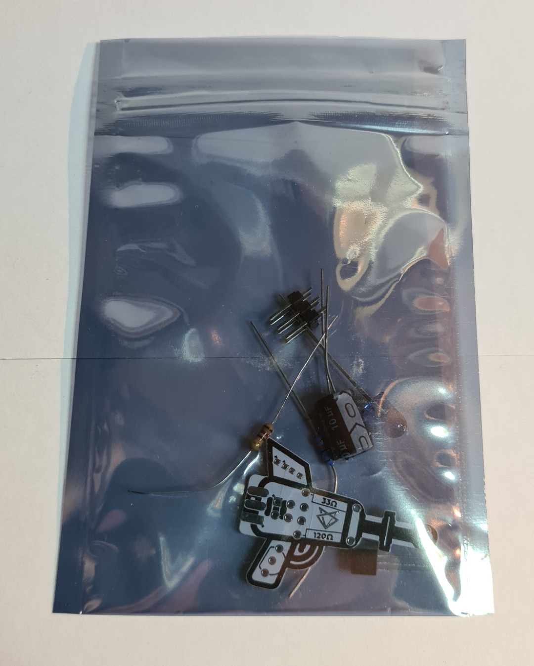
All components neatly packaged
-
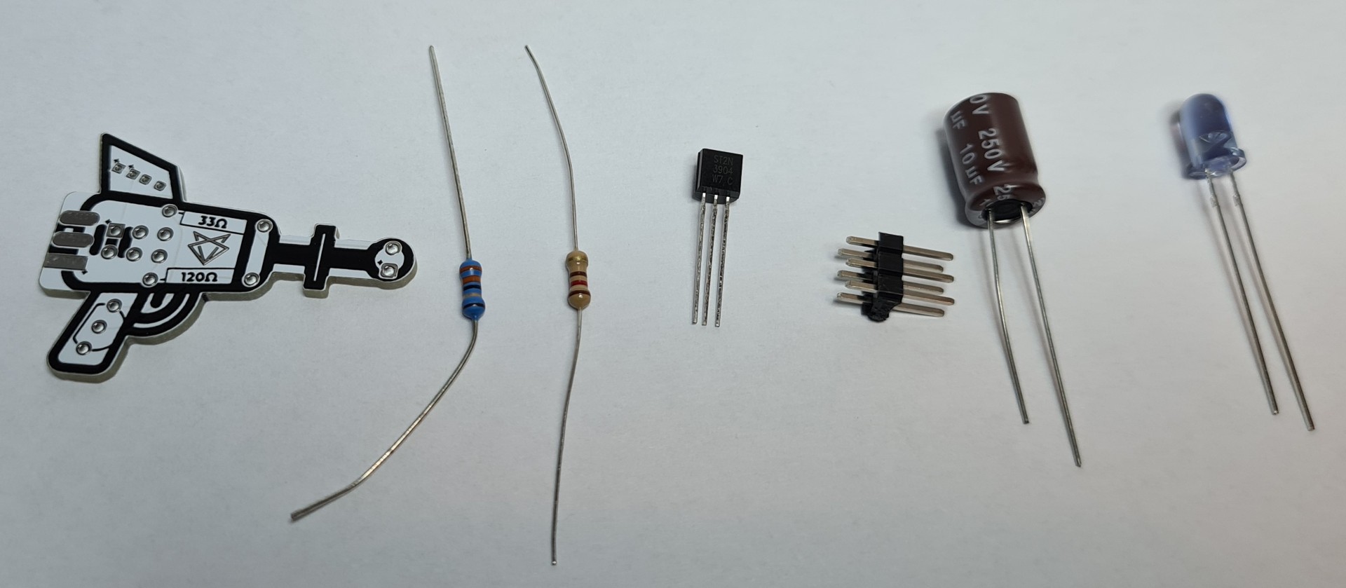
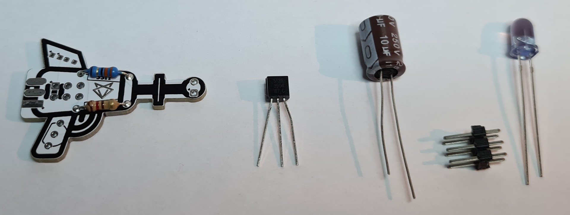
Spread out in order of soldering
-
Component side of the pcb is where the fri3d logo is
- 33 Ohm (blue body and orange,orange.black colored bands) resistor on top
- 120 Ohm (beige body and brown, red, brown colored bands) risistor on bottom
2 resistors soldered
-
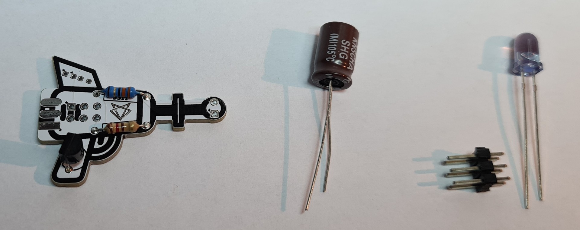
NPN transistor 2N3904 with flat side to the right (front of noisy cricket). This is different from the silkscreen on the pcb.
transistor is wrongly soldered in these pictures
-
Electrolytic capacitor (33 microFarad)
Mind the polarity: long leg is positive, short leg is negative, white marking on the body is negative
There are 2 holes for positive and 2 holes for negative, choose best fitting ones. transistor is wrongly soldered in these pictures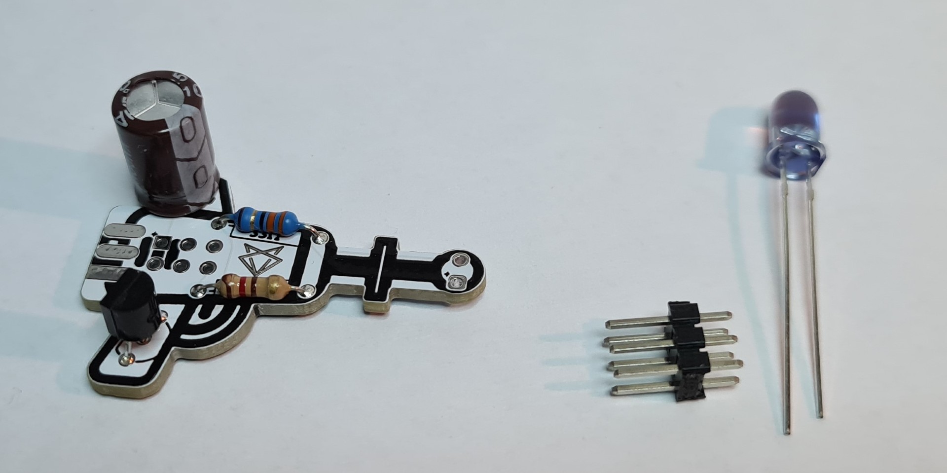
-
Pin header soldered on the bottom
2 orientations are possible:- on the bottom: this results in an upright position when mounted on the fri3d2024 badge
- at the back: this results in a front facing position when mounted on the fri3d2024 badge
transistor is wrongly soldered in these pictures
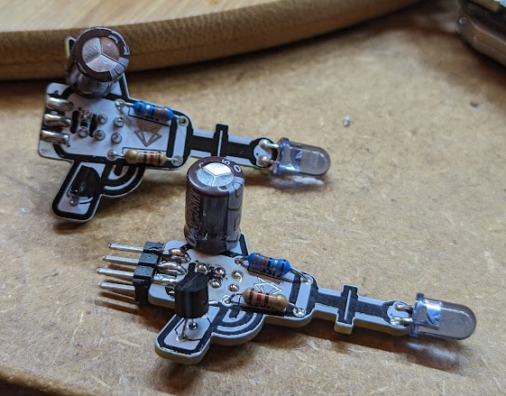
-
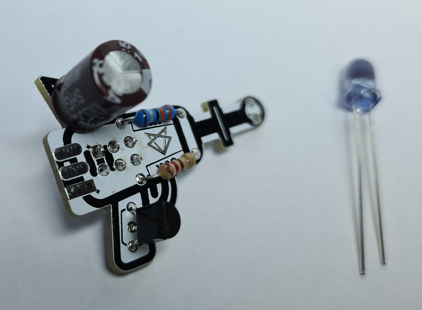
Ready to solder the LED
Mind the polarity: long leg is positive, short leg is negative, flat side on the body is negative transistor is wrongly soldered in these pictures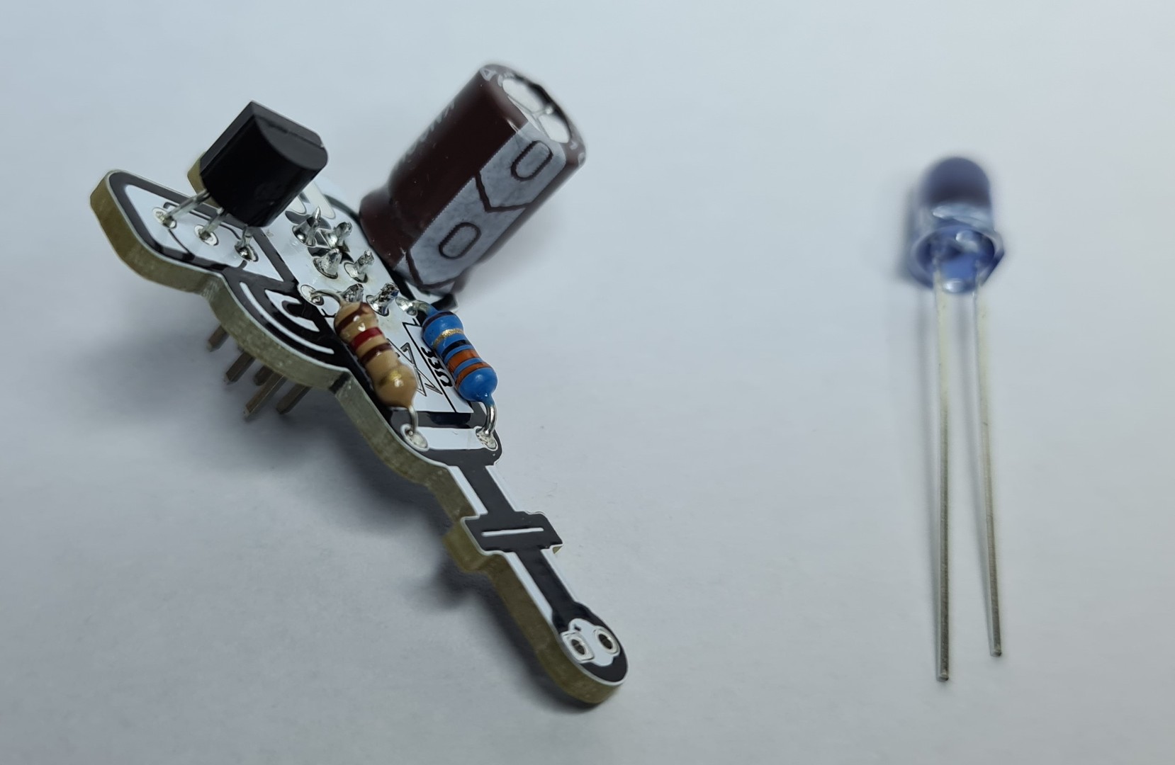
-
LED soldered
Mind the polarity: positive (long leg) on the bottom, negative on top (short leg, flat side on the body) transistor is wrongly soldered in these pictures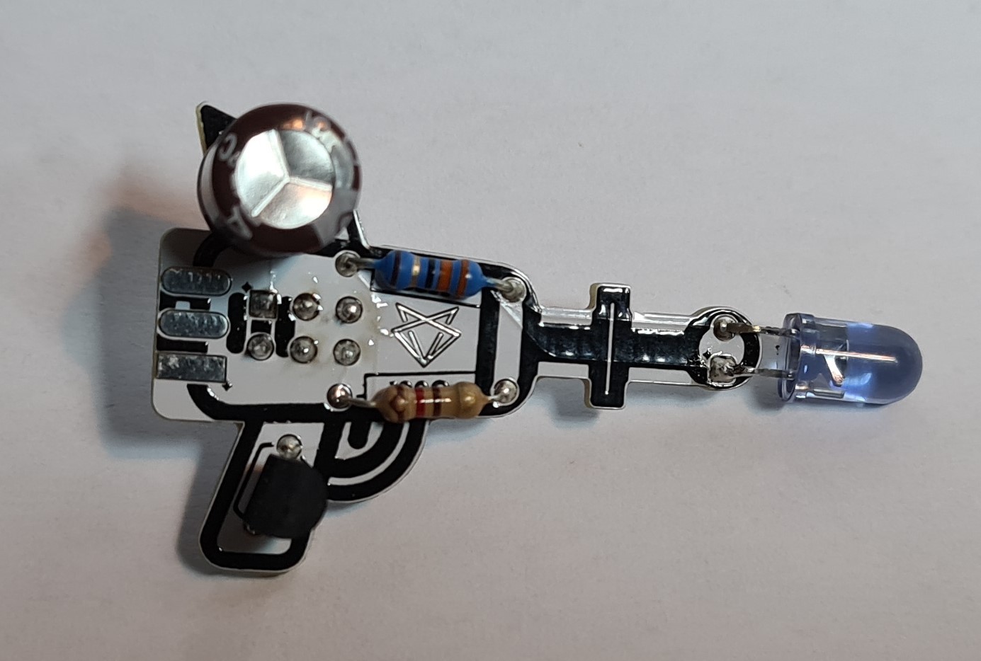
-
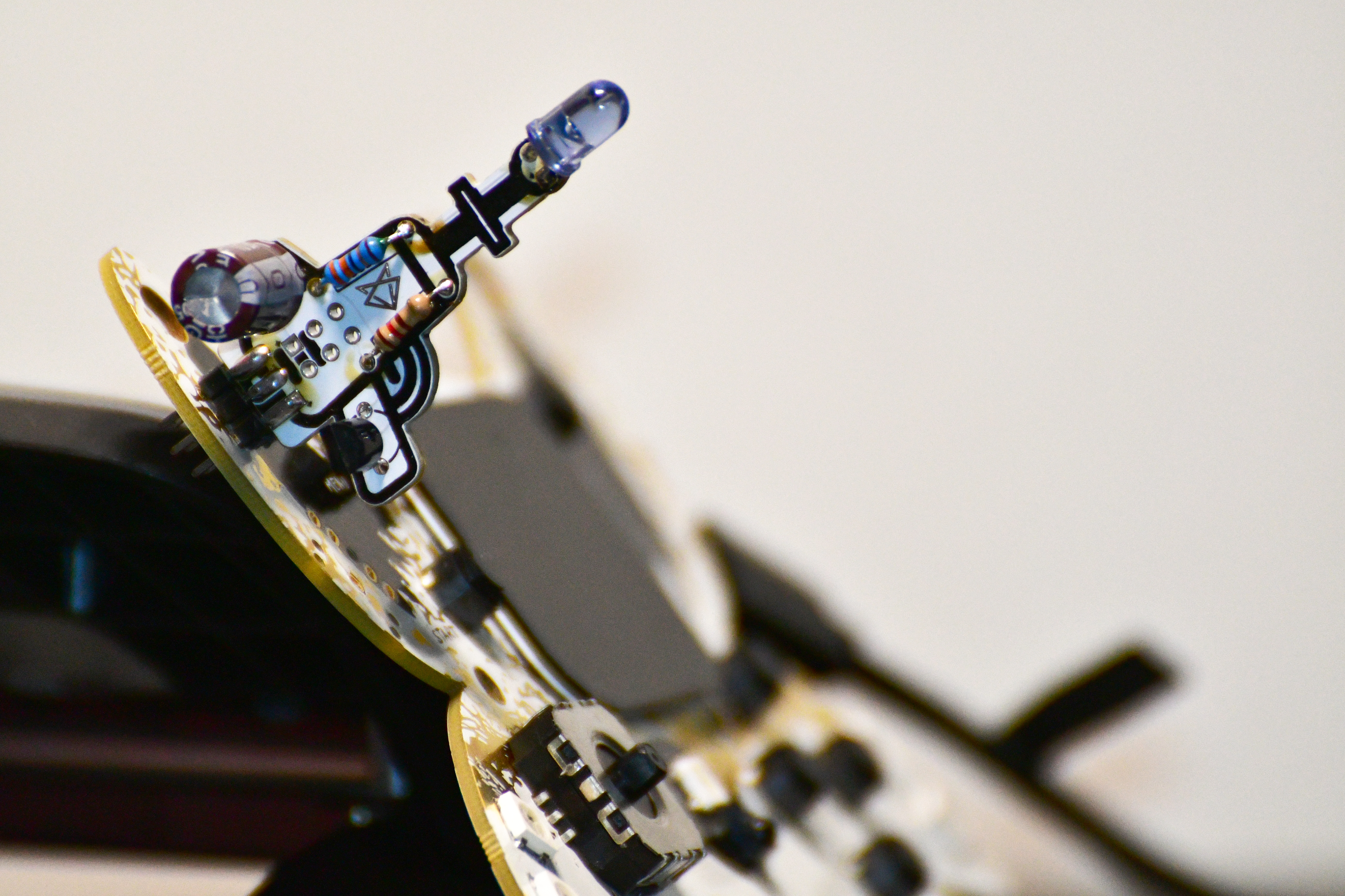
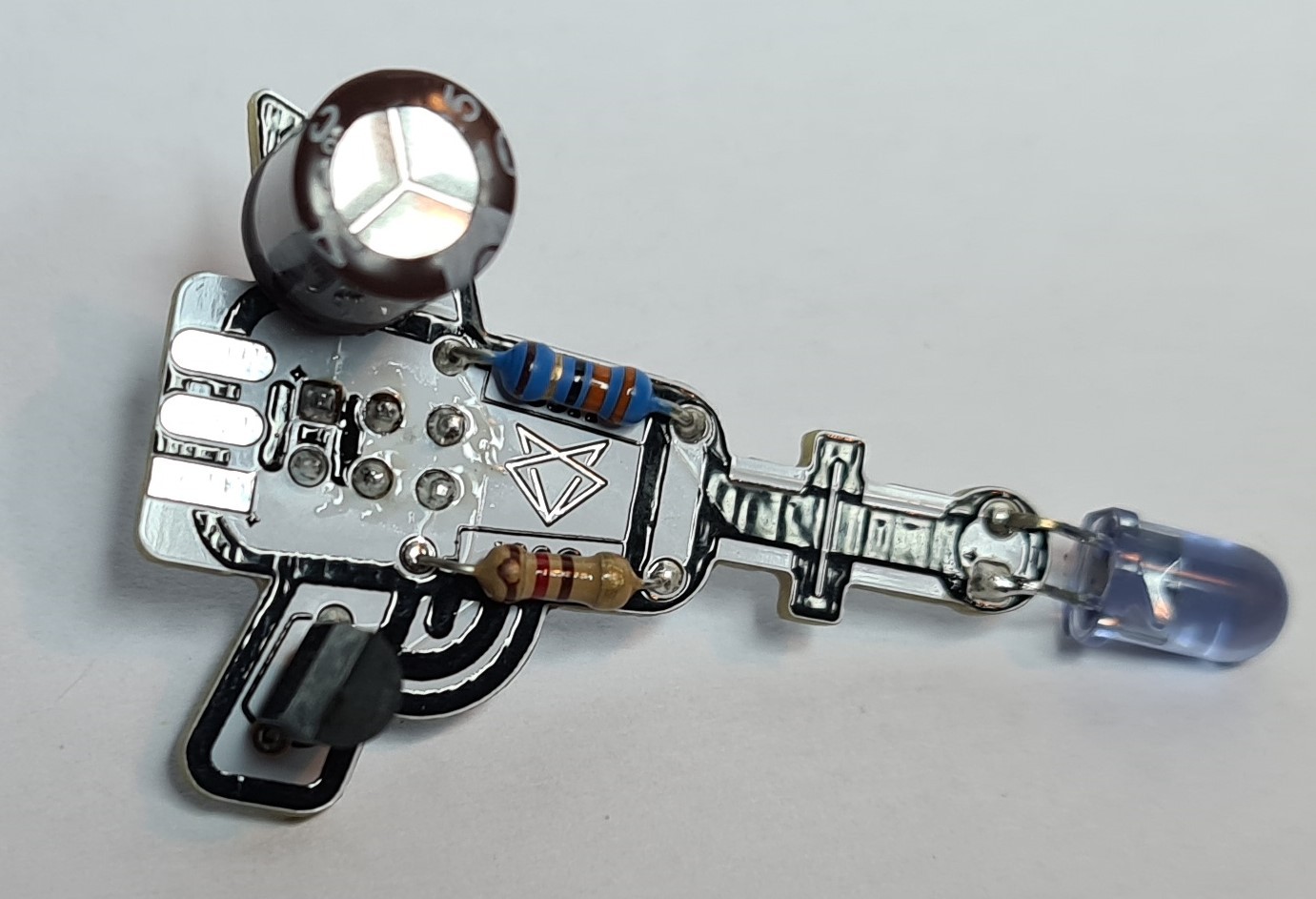
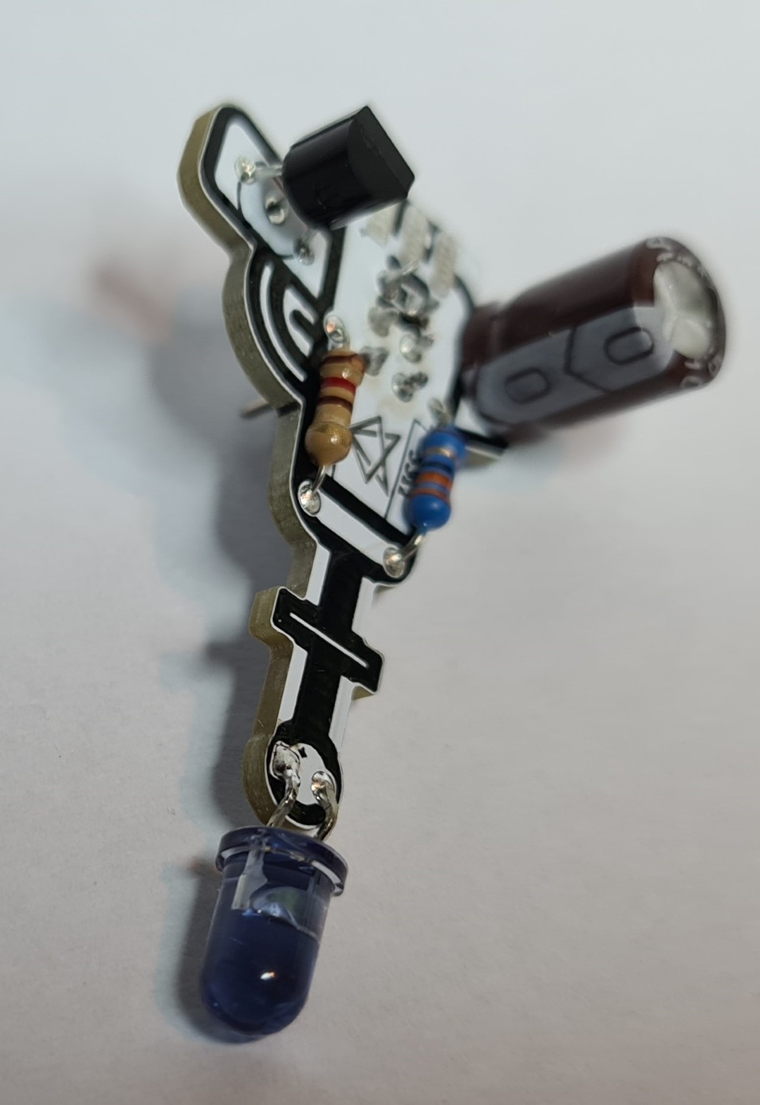
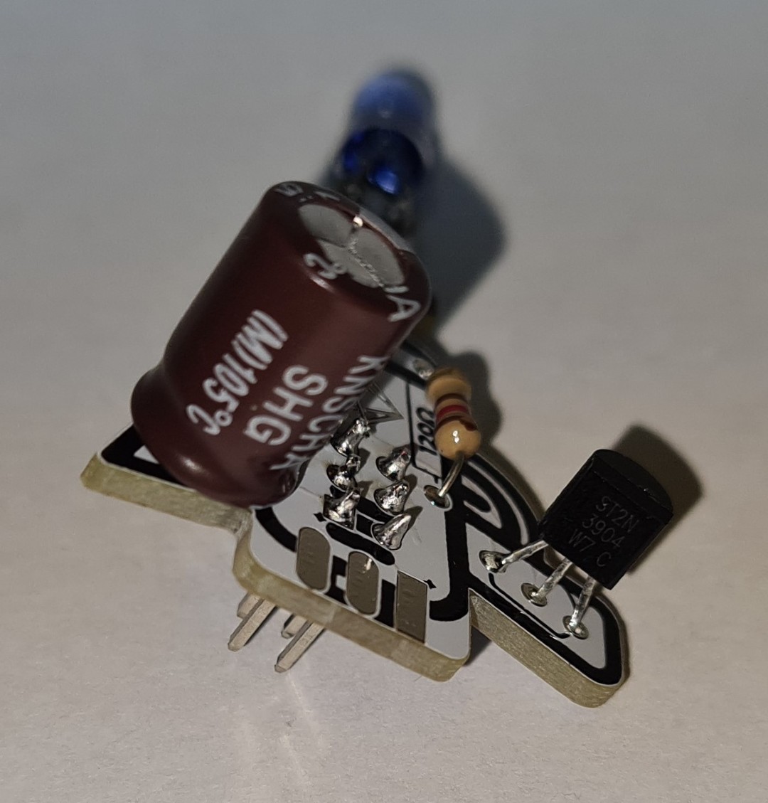
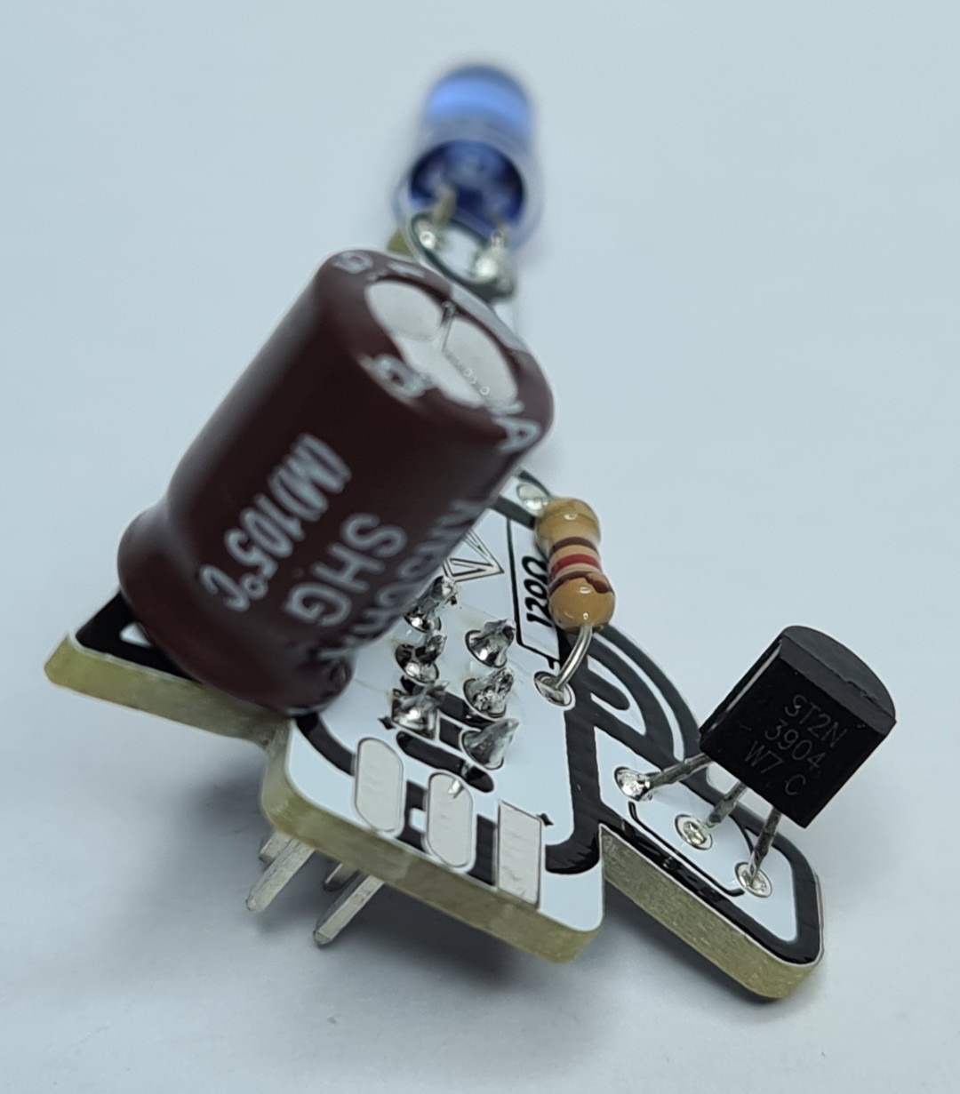
Overview pictures of soldered Noisy Cricket transistor is wrongly soldered in these pictures
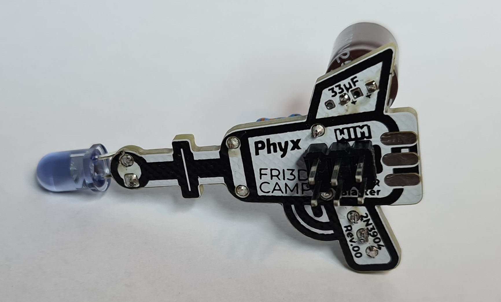
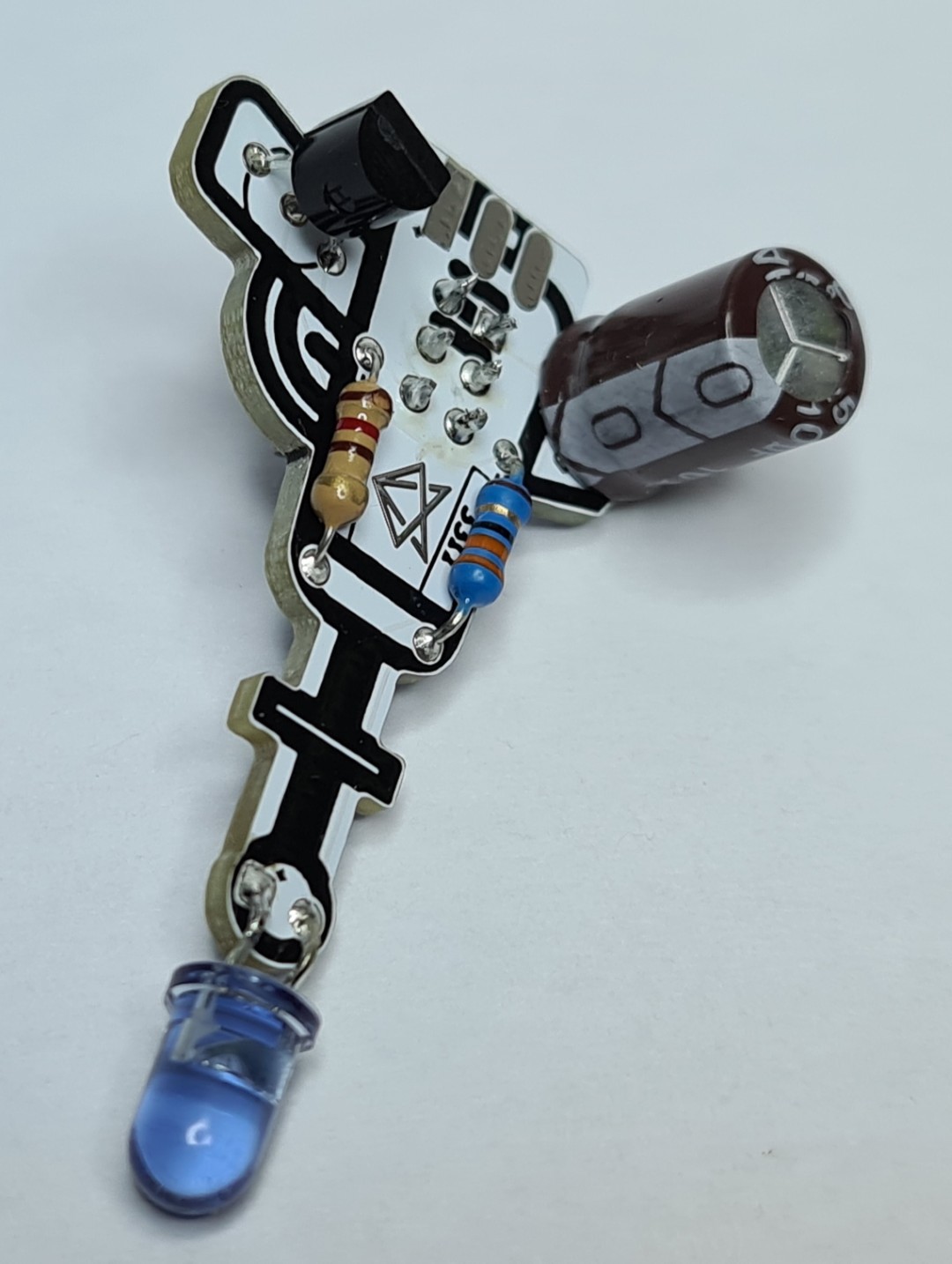
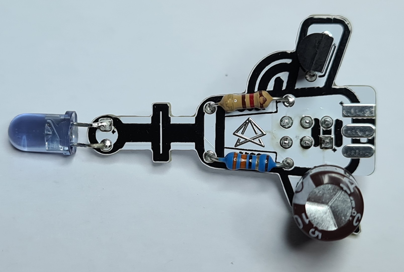
-
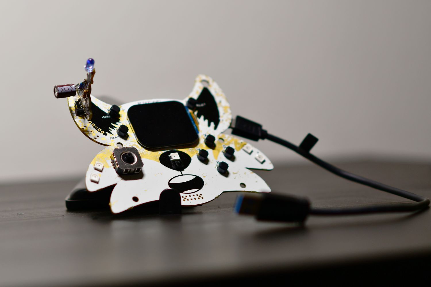
Noisy Cricket mounted on the fri3d2024 badge Mounted with the pin header soldered on the bottom transistor is wrongly soldered in these pictures
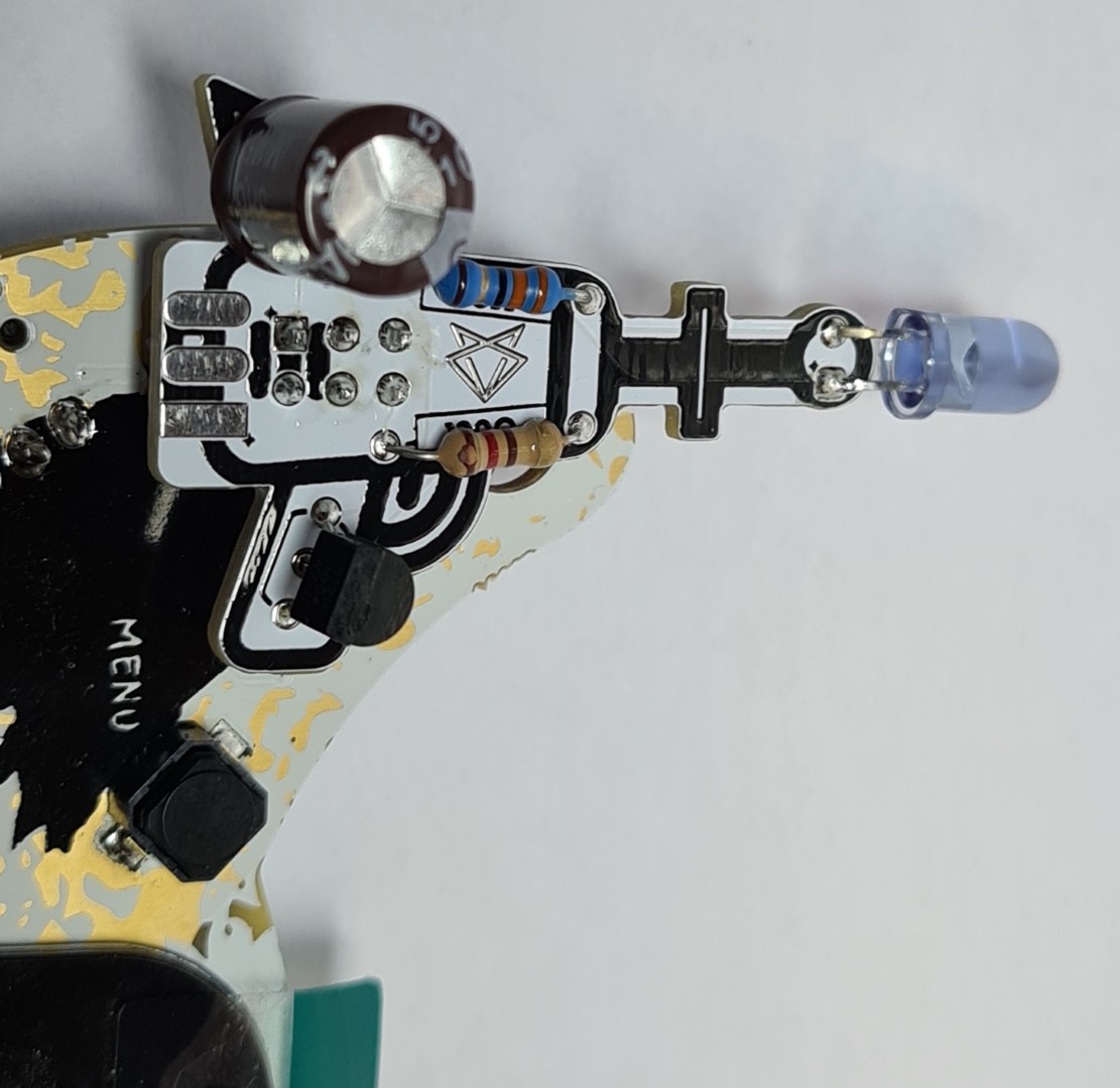
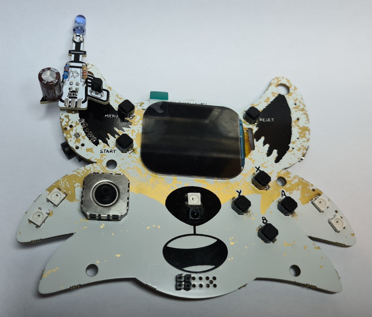
Mounted with the pin header soldered on the back transistor is wrongly soldered in these pictures